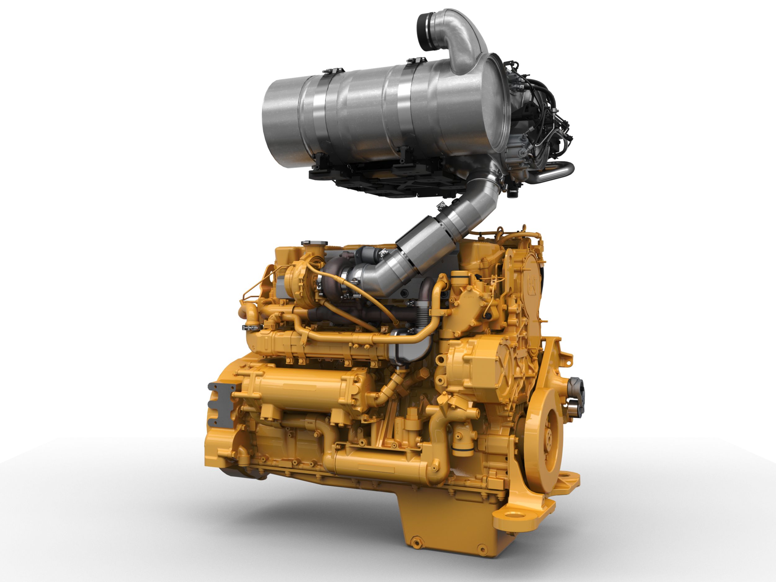
C9 ACERT™ Hazardous Location Engine
- new - Products
- C9 ACERT™ Hazardous Location Engine
At a glance data:

Overview
Cat C9 ACERT hazardous location engines are the ideal solution for specialized and demanding operations in the oilfield. Engines are hazardous-location certified from the factory to minimize installation design, time, and cost. Decades of field operation and intense research and development allow Cat C9 ACERT hazardous location engines to deliver excellent performance with low operating costs and emissions.Hazardous location engines are certified to operate in potentially explosive environments. Applications powered by C9 ACERT engines include workover rigs, pump skids, acidizing units, cementing units, coil tubing units, and hydraulic power units. Cat engines are backed by the worldwide network of Cat dealers ready to support your operation with technical support, service, parts, and warranty. C9 ACERT hazardous location engines, with ratings 254 bkW (340 bhp) @ 2200 rpm meet IMO Tier II, EPA Non-road Tier 3 equivalent and EU Stage IIIA equivalent emission standards. They are available using U.S. EPA and EU Flexibility, and for other regulated and non-regulated areas.
General Specifications
Emissions
Dimensions
Capacity for Liquids
Standard Equipment
air inlet system
- Turbocharger, separate circuit (SCAC) or remote (REMAC) aftercooler
- Single, right-side, center-mounted turbo with water-cooled turbine housing
- Air inlet 101.6 mm (4 in) connection type
control system
- Electronic governing, PTO speed control
- Programmable ratings
- Cold mode start strategy
- Automatic altitude compensation
- Fuel cooled ECU
- Power compensation for fuel temperature
- Programmable low and high idle
- Electronic diagnostics and fault logging
- Programmable monitoring system (engine speed, temperature, pressure)
- J1939 broadcast (diagnostic and engine status)
- Certified electrical control system (hazardous environment only)
- Derated engine: automatic ambient temperature compensation
cooling system
- Thermostats and housing, RH forward-facing outlet — 51 mm (2.01 in) connection
- Jacket water pump — belt-driven, centrifugal
- Water pump — inlet RH facing downward 63 mm (2.48 in)
exhaust system
- Exhaust manifold — wet
- Single, right-side, center-mounted turbo with water-cooled turbine housing
- Rear facing turbo exhaust 81.8 mm (3.22 in.) connection, non V-band clamp
flywheels and flywheel housing
- Mandatory selection of:SAE No. 1 or SAE No. 2 flywheel and housing, SAE standard rotation
fuel system
- HEUI fuel system
- Fuel filter — secondary, LH (2-micron high performance)
- Fuel transfer pump — left front
- Fuel priming pump — left front
lube system
- Crankcase breather — LH
- Crankcase fumes disposal — with integrated service indicator, LH
- Oil cooler — RH
- Oil filter — RH
- Oil pan — front sump
- Oil filler — top mounted
- Oil level gauge — LH side
- Oil pump — gear-driven
- Oil valve sampling
- Preservation of turbocharger, flywheel, and crankcase
power take-offs
- Crankshaft drive pulley — 2 grooves, 190 mm (7.5 in) diameter, 22.3 mm (7/8 in) wide
general
- Vibration damper
- Lifting eyes
- Automatic variable timing — electronic
- Literature
mandatory options
- Flywheel housing and flywheel
- Primary filter/water separator
- Turbo orientation
Optional Equipment
air inlet system
- Air inlet elbow
- Air shutoffs
cooling system
- Water outlet elbow
- Coolant conditioner
flywheels and flywheel housing
- Crankshaft seal
instrumentation
- Gauges and instrument panels
- Interconnect harness
lube system
- Oil pans
- Drain and cover
- Remote oil filters
- Lubricating oils
mounting system
- Structural steel base
- Engine support — front and rear
power take-offs
- Rear enclosed clutches
- Hydraulic pump drives
- Hydraulic gear pumps
- Clutch supports
- Crankshaft pulleys
- Transmission Arrangement
- General
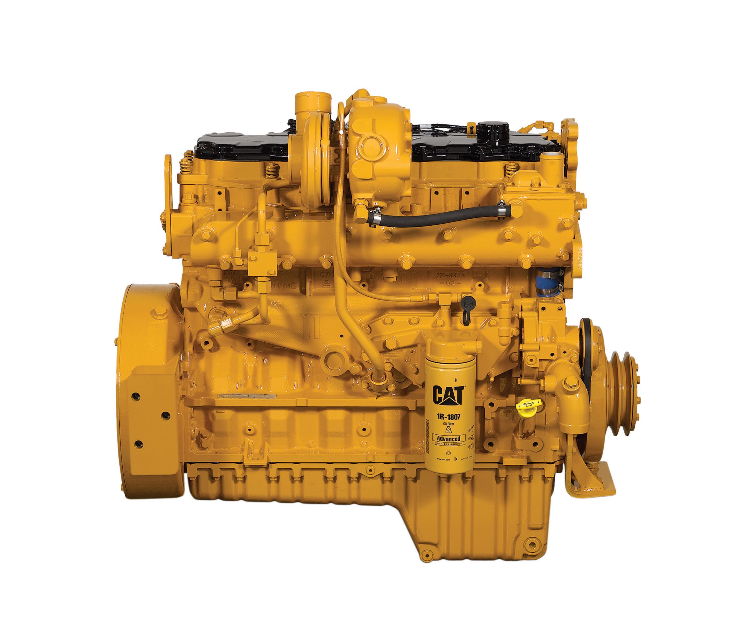
C7 ACERT™ Water-Cooled Manifold Engine
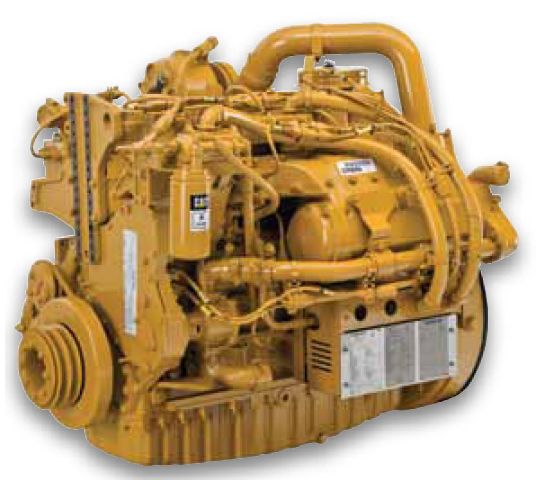
C7 ACERT™ Hazardous Location Engine

C7 ACERT™ Dry Manifold Engine
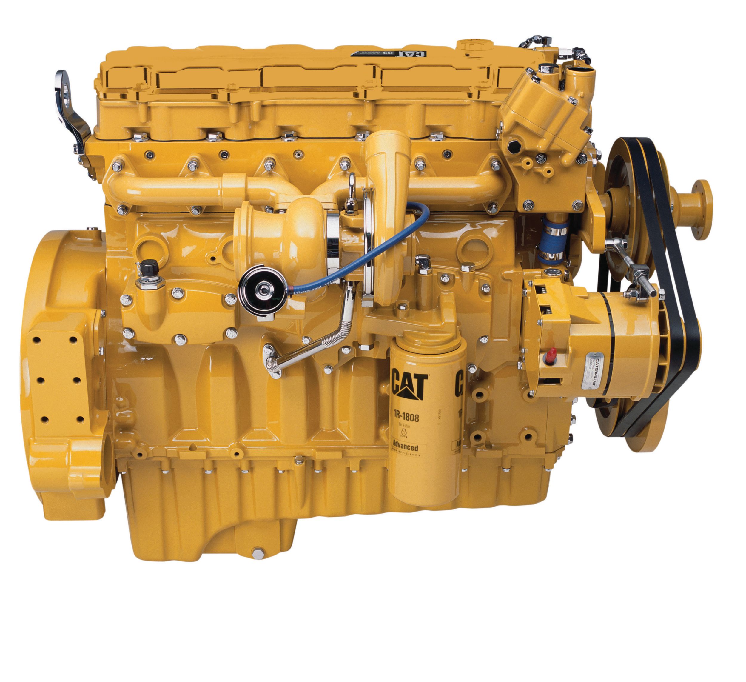
C9 ACERT™ Dry Manifold Engine

C9 ACERT™ Water Cooled Manifold Engine
C11 ACERT™ Dry Manifold Engine
C13 ACERT™ Dry Manifold Petroleum Engine
Similar Products
C9.3 ACERT™ Tier 4 Final Engine
3516C (HD) Well Stimulation Engine
